Single mode vs. multimode fiber optic cables: What are the differences?
In today’s telecommunications systems and network infrastructure, fiber optic cables are an indispensable transmission solution thanks to their high speed, stable performance, and long-distance transmission capability. Based on the principle of light propagation within the fiber core, fiber optic cables are generally classified into two main types: single mode fiber and multimode fiber. Each type is designed to meet different technical requirements and application ranges.
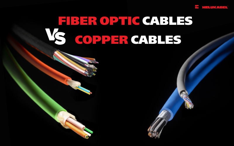
Fiber optic cables are often regarded as the gold standard in network cabling infrastructure. Compared with copper cables, fiber optics deliver superior performance, enabling data transmission over much longer distances while significantly minimizing signal attenuation and quality degradation.
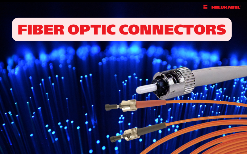
Fiber optic cables are available in a wide range of types, structures, and designs, and they can be terminated with different kinds of connectors at each end. Depending on the required transmission distance and the expected network performance, selecting the appropriate type of fiber optic cable is essential. Today, there are two main types of fiber optic cables commonly used to interconnect network devices: single mode fiber and multimode fiber.
1. Understanding single mode fiber optic cables
Structure of single mode optical cable
1.1 What are single mode fiber optic cables?
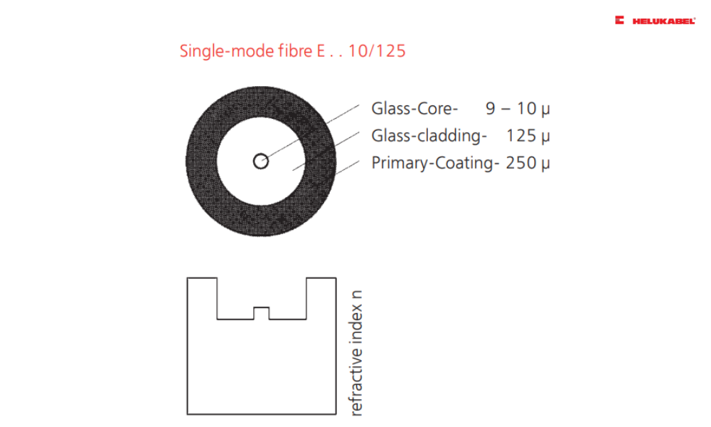
This type of fiber optic cable allows only a single light ray to travel at any given time. Typically, single mode fiber features a very small core diameter of approximately 9 µm and operates efficiently at 1310 nm and 1550 nm wavelengths.
Because of its small core diameter, light in a single mode fiber propagates in only one mode, which significantly reduces internal light reflection and modal dispersion. As a result, signal attenuation is minimized, allowing data to be transmitted over much longer distances compared to other types of fiber optic cables.
Signals such as cable television, Internet, and telephone communications are commonly transmitted via single-mode fiber, with multiple fibers bundled together into large-capacity backbone cables. Single-mode fiber is primarily used for long-distance transmission. However, at higher transmission speeds, the cost of single mode fiber cables and the associated optical equipment is generally higher than that of multimode fiber solutions.
1.2 Structure of single mode fiber optic cables
Single mode fiber optic cable consists of the following main components:
- Core: The core is located at the center of the optical fiber and is responsible for guiding light signals. For single-mode fiber, the core diameter typically ranges from 8.3 µm to 10 µm.
- Cladding: The cladding surrounds the core. Both the core and the cladding are made of fused silica glass. The refractive index of the cladding is always lower than that of the core. This difference in refractive indices keeps the light confined within the core and prevents signal leakage. The cladding diameter of single-mode fiber is approximately 125 µm.
- Buffer / Coating: The buffer layer, also known as the coating, is made from specially engineered materials to protect the optical fiber and cladding from mechanical stress and damage. In addition, it helps minimize micro-bending, which is a common cause of signal loss due to light scattering.
- Outer jacket: The outer jacket is the final protective layer of the fiber optic cable. It shields the internal components from external environmental factors such as moisture, temperature variations, and physical impact. In addition, the jacket typically provides identification information about the cable type.
1.3 Types of single mode fiber optic cables
Single mode cables are classified into OS1 and OS2.
| OS1 | OS2 | |
| Standard | ITU-T G.652A/B/C/D | ITU-T G.652C/G.657.A1 (part) |
| Cable structure | Tight buffer | Loose buffer |
| Application | Indoor | Outdoor |
| Attenuation | 1.0 dB/km | 0.4 dB/km |
| Maximum distance | 10 kilometers | 200 kilometers |
| Cost | Low | High |
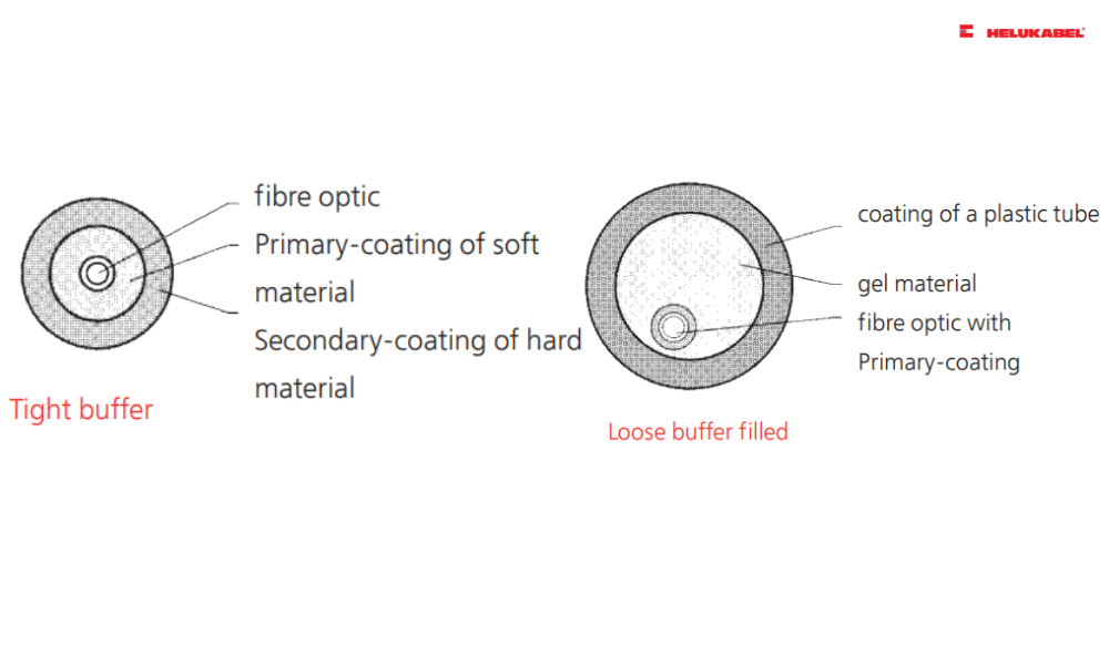
The difference between OS1 and OS2 optical cables lies in the buffer layer.
OS1 fiber optic cable is a tight-buffered single-mode cable, primarily designed for indoor applications, where transmission distances are typically shorter but EMI may be higher. OS1 cables are generally used for distances of up to 10 km and support transmission speeds of up to 10 Gbps. Compared to OS2, OS1 cables are more cost-effective.
In contrast, OS2 fiber optic cable is engineered for outdoor environments and long-distance transmission applications, with a maximum reach of up to approximately 200 km. OS2 also supports higher bandwidth, reaching up to 100 Gbps, and therefore comes at a higher cost compared to OS1.
Beyond performance differences, OS2 cables feature a distinct construction design. They utilize a loose-tube structure, in which the optical fibers are arranged in a helical pattern inside semi-rigid tubes. This design allows the cable to stretch and flex without placing tensile stress on the glass fibers, thereby enhancing durability and installation stability in outdoor conditions. Overall, OS2 is the highest-performance single-mode fiber option for long-distance transmission, offering superior durability and reliability for demanding network infrastructures.
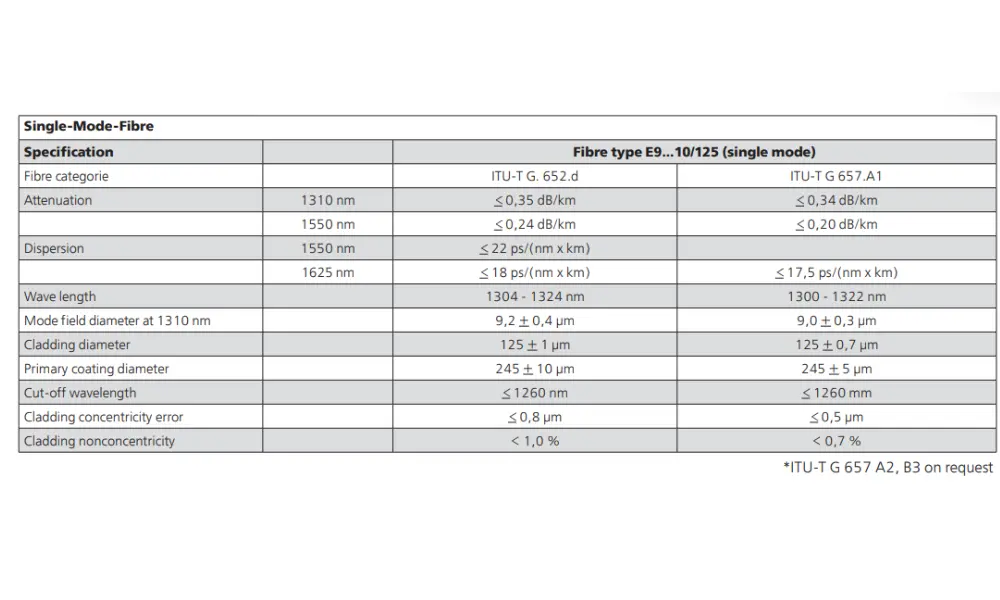
The two ITU standards applied to HELUKABEL's fiber optic products are ITU-T G.652.d and ITU-T G.657.A1.
1.4 ITU standards for single mode fiber optic cables
To facilitate fiber optic communications, the International Telecommunication Union (ITU) has established a comprehensive system of standards for different types of optical fibers.
For HELUKABEL single-mode fiber optic products, the two applicable ITU standards are ITU-T G.652.D and ITU-T G.657.A1.
2. Understanding multimode fiber optic cables
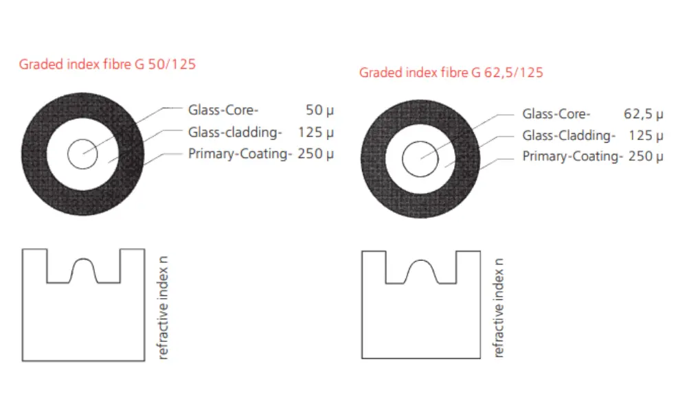
Structure of multimode fiber optic cable
2.1 What are multimode fiber optic cables?
Multimode fiber optic cables are characterized by a much larger core diameter, typically 50 µm or 62.5 µm, allowing multiple data streams to be transmitted simultaneously within a single fiber. Thanks to this design, multimode fiber can use lower-cost light sources such as LEDs or VCSEL (Vertical-Cavity Surface-Emitting Laser) transmitters, making multimode solutions significantly more affordable than single mode fiber.
However, the larger core also means that light reflects more frequently within the fiber, creating multiple propagation paths (modes) for the transmitted signals. While this enables parallel transmission of multiple signals, it also results in higher modal dispersion and greater signal attenuation.
Due to this higher attenuation, multimode fiber cannot support transmission distances as long as single mode fiber. When longer distances are required, multimode-based systems often need additional amplification or signal enhancement equipment, which limits scalability compared to solutions based on single mode fiber.
2.2 Structure of multimode fiber optic cables
Multimode fiber optic cables have a structure similar to that of single mode fiber, consisting of key components such as the core, cladding, buffer, coating, and jacket.
However, the main structural difference between single mode and multimode fiber lies in the core diameter. Multimode fiber features a larger core, typically ranging from 50 µm to 62.5 µm, depending on the specific multimode fiber type.
2.3 Types of multimode fiber optic cables
Multimode fiber optic cables are primarily used for short-distance transmission, typically under 500 meters. Based on technical standards and bandwidth performance, multimode fiber is commonly classified into OM1, OM2, OM3, and OM4.
- OM1 is the lowest-performance but most cost-effective multimode fiber type, supporting a maximum bandwidth of 10 Gbps over a distance of approximately 30 meters.
- OM2 provides improved link quality and can maintain the same 10 Gbps performance over distances of up to around 80 meters.
- OM3 further enhances transmission capability, allowing 10 Gbps data rates over distances of up to 300 meters.
- OM4 offers the highest performance among these types, supporting 10 Gbps transmission over distances of up to 1,400 meters. In addition, OM4 can support higher data rates such as 40 Gbps and 100 Gbps over distances of up to 150 meters.


3. Differences between single mode and multimode fiber optic cables

The light transmission mechanisms in single mode and multimode optical fiber cables are completely different.
3.1 Light propagation mechanism
The way light propagates in single mode and multimode fiber is fundamentally different.
- Multimode fiber supports two types of light propagation: step-index and graded-index.
- Single-mode fiber supports only one propagation type: step-index.
Thanks to this characteristic, single mode fiber experiences significantly lower attenuation and signal degradation. As a result, single mode fiber allows more stable signal transmission over much longer distances.
3.2 Core diameter of single mode and multimode fiber optic cables
The most obvious difference between single mode and multimode fiber optic cables lies in the core diameter. Single-mode fiber features a much smaller core compared to multimode fiber.
Specifically, the core diameter of single-mode fiber is typically around 9 µm, while multimode fiber has a core diameter of 50 µm or 62.5 µm.
This smaller core diameter significantly reduces signal attenuation, enabling single-mode fiber to transmit data over much longer distances than multimode fiber.
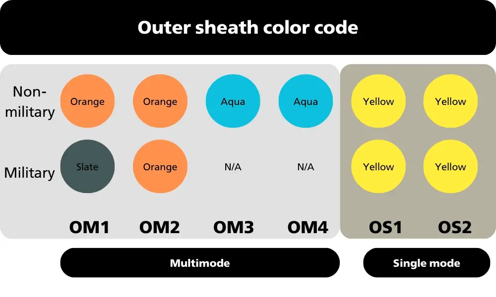
Distinguish between single mode and multimode fiber optic cables based on jacket color (TIA-598C standard)
3.3 Distinguishing single mode and multimode cables by jacket color
Jacket color is one of the quickest ways to identify single mode and multimode fiber optic cables in practical installations.
According to the TIA-598C standard for non-military applications, single mode fiber is typically identified by a yellow jacket, while multimode fiber commonly comes with an orange or blue jacket.
However, in real-world applications, jacket color does not always accurately indicate the fiber type. Some manufacturers may use different jacket colors to align with internal standards, specific product lines, or alternative technical specifications. Therefore, distinguishing fiber optic cables solely based on jacket color is only valid under certain standards and should always be verified against technical documentation.
3.4 Bandwidth differences
The difference in bandwidth performance between single mode fiber and multimode fiber mainly stems from the fiber core structure and the light propagation mechanism within the fiber.
- Step-index multimode fiber: This type of fiber offers low bandwidth, typically below 100 MHz/km. It is only suitable for very short-distance links (under 500 m) and does not perform well in high-speed data transmission applications.
- Graded-index multimode fiber: With an improved refractive index profile, this fiber achieves higher bandwidth, usually below 1 GHz/km. Reduced pulse spreading allows it to operate efficiently over medium distances, generally above 500 m.
- Single mode fiber: Single mode fiber delivers superior bandwidth performance, with bandwidths reaching below 10 GHz/km. Because it supports only one light propagation mode, there is no modal dispersion, allowing signals to maintain high quality over very long distances.
| Step-index multimode | Graded-index multimode | Single mode | |
| Bandwidth | < 100 MHz/km | < 1 GHz/km | < 10 GHz/km |
| Dispersion | 10–150 ns/km | 1–5 ns/km | 4–150 ns/km |
| Travel distance | Long impulse spreading for short distances < 500 m | Short impulse spreading for middle distances > 500 m | No impulse spreading for long distances > 500 m |
| Attenuation | Middle – High | Low | Very low |
3.5 Transmission distance
In multimode fiber, each light ray travels along a different path and reaches the end of the fiber at different times, causing modal dispersion. This phenomenon limits both the available bandwidth and the transmission distance. As a result, the maximum transmission distance of multimode fiber is typically around 300 - 500 meters.
For single mode fiber, the very small core significantly minimizes dispersion and allows high-bandwidth transmission over much longer distances. Thanks to this characteristic, single-mode fiber can be used for transoceanic data transmission, forming the backbone of the global Internet infrastructure. In practical deployments, single mode fiber can support 1Gb Ethernet transmission over distances of up to 5000 meters.


3.6 Cost comparison between single mode and multimode fiber optic cables
When designing a fiber optic cabling system, it is essential to consider both the transmission distance and the cost of optical transceivers and fiber cables. In general, single mode fiber optic cables themselves are often less expensive than multimode fiber cables; however, other system components in single-mode solutions can be more costly compared to multimode-based systems.
To fully leverage the advantages of single mode fiber, it is typically deployed in long-distance transmission applications. As a result, the system requires laser-based optical transceivers, which increases the initial investment cost. In most cases, single-mode transceivers are more expensive than those used for multimode fiber.
In many large-scale data centers, multimode fiber solutions are often preferred due to lower transceiver costs and reduced power consumption. In contrast, for submarine communication systems, single mode fiber is the standard choice thanks to its long transmission reach and high reliability.
4. HELUKABEL single mode and multimode fiber optic cable portfolio
HELUKABEL offers a comprehensive portfolio of singlemode and multimode fiber optic cables, fully addressing data transmission requirements across industrial environments, data centers, telecommunications systems, and modern network infrastructure.
HELUKABEL fiber optic cables are designed in compliance with international standards such as ISO/IEC, ITU-T, and TIA/EIA, ensuring low attenuation, high mechanical durability, and stable transmission performance across a wide range of installation conditions, ranging from indoor to outdoor environments, and from static installations to harsh industrial applications.
4.1 Overview of our fiber optic cable portfolio
For most applications, HELUKABEL fiber optic products are available in both singlemode and multimode variants. These fiber optic cables are engineered to serve a broad spectrum of use cases, including:
| Application | Description |
| Indoor | Designed for low mechanical stress environments. These cables feature lighter protective layers, making them more cost-effective than outdoor cables. They are widely used in buildings, offices, and residential networks for internal LAN and structured cabling systems. |
| Outdoor | Built with a more robust structure and significantly higher mechanical strength than indoor cables. Reinforced protective layers ensure reliable transmission performance and long service life in outdoor environments. |
| Direct burial | Installed directly underground, typically at depths of 0.8 to 1.2 meters. These cables are engineered to resist dust, soil erosion, moisture, and especially rodent or insect damage. |
| Aerial cables | Installed on utility poles or along building facades. As they are directly exposed to environmental conditions such as wind, rain, ice, and storms, these cables are more susceptible to mechanical stress compared to direct burial or duct-installed fiber cables. |
| Universal cables | Designed to meet the requirements of both indoor and outdoor installations. These cables combine installation safety and flexibility with high capacity and durability for outdoor conditions. |
| Industrial applications | Various types such as GOF, HCS, POF |
4.2 Common single mode fiber optic cables
HELUKABEL offers a wide range of single mode fiber optic cables to meet needs ranging from internal networks to telecommunication infrastructure and long-distance transmission systems. All HELUKABEL single mode fiber optic cables are manufactured in accordance with the international ITU-T G.652 (9/125 µm) standard.
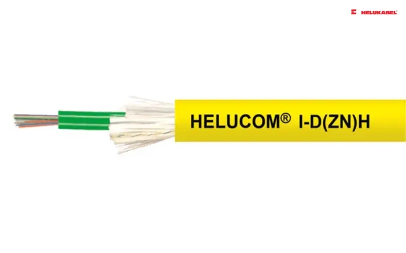
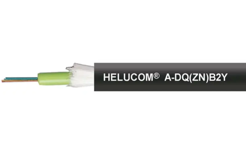
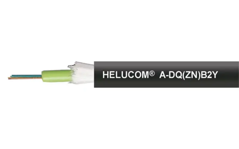
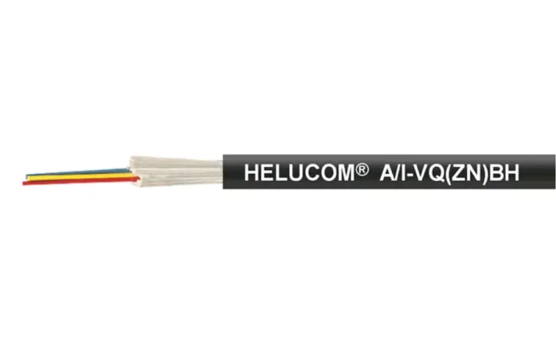
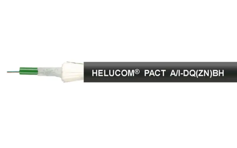
| 4Fo (4-fiber) single mode fiber optic cable | I-V(Zn)H ( 80430); A/I-VQ(Zn)BH (82814); A/I-DQ(Zn)BH (801219); A-DQ(Zn)B2Y (802138) |
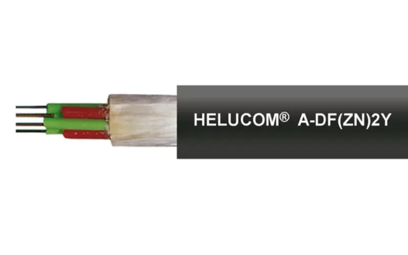
| 8Fo (8-fiber) single mode fiber optic cable | I-V(Zn)HH ( 80816); A/I-DQ(Zn)BH (82802); A-DQ(Zn)B2Y (80183); A-DF(Zn)2Y4Y (80118) |
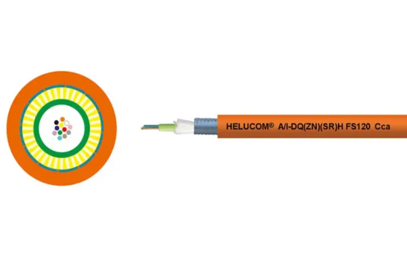
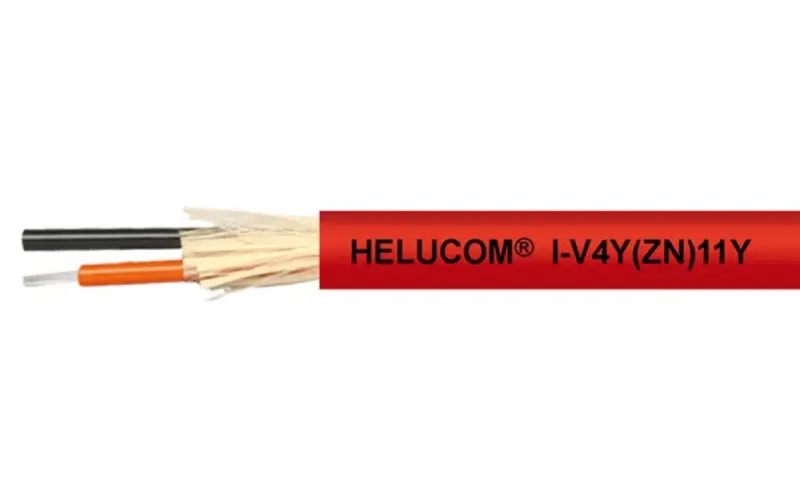
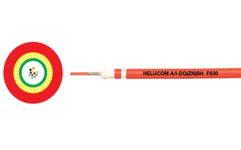
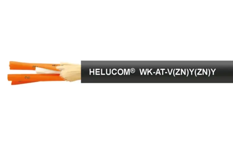
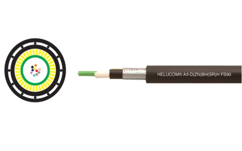
| 12Fo (12-fiber) single mode fiber optic cable | I-V(ZN)H ( 80418); A/I-DQ(ZN)BH (80279); A/I-D(ZN)BH(SR)H (803920); AT-V(ZN)H(ZN)11Y (804700) |
| 24Fo (24-fiber) single mode fiber optic cable | I-D(ZN)H ( 80902); A/I-DQ(ZN)BH (80846); A-DF(ZN)2Y(SR)2Y (805245); A-DQ(ZN)(SR)2Y (804797) |
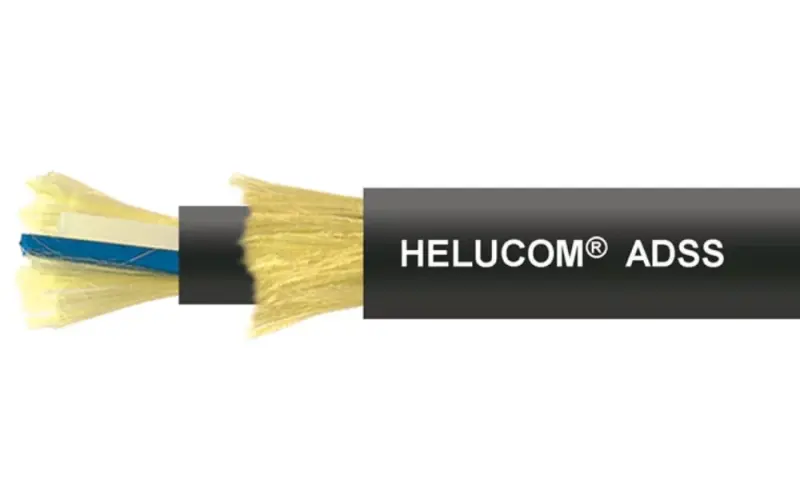
| ADSS aerial single mode fiber optic cables | HELUCOM® ADSS L ( 804733); HELUCOM® ADSS (82390) |
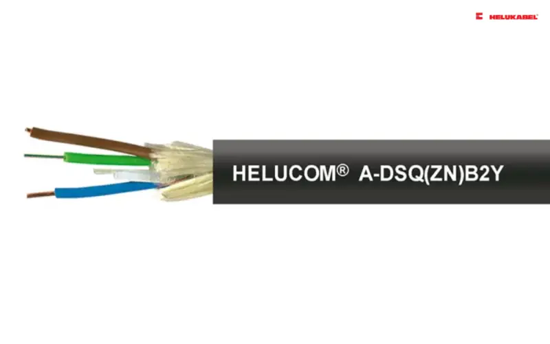
| Single mode cables for outdoor use, rodent protection, direct burial | A-DSF(L)(ZN)2Y ( 80495); A-DSQ(ZN)B2Y (81260); A-DF(ZN)2Y(SR)2Y (803284); A-DF(ZN)2Y(SR)2 (805244); A-DF(ZN)2Y4Y (80959) |
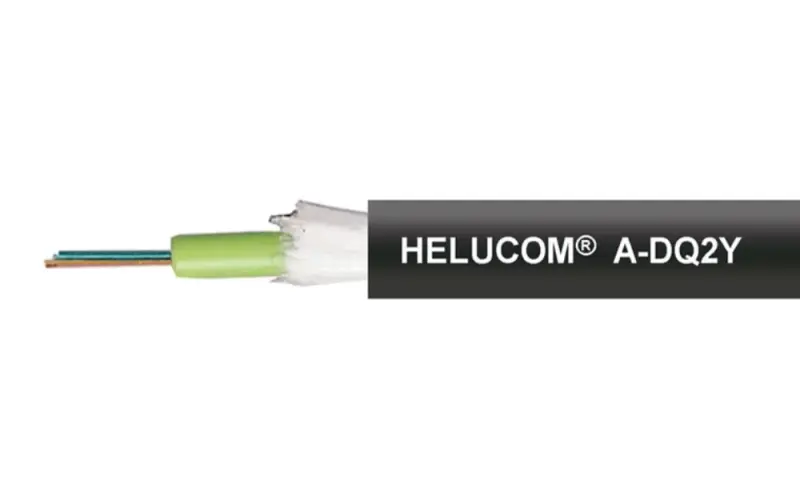
| Microduct cables (FTTH applications) | A-DQ2Y, central ( 803664); A-DQ2Y, stranded (803931) |
In addition, HELUKABEL also offers single mode fiber optic cables in various fiber counts, including 1 fiber, 2 fibers, 10 fibers, 48 fibers, 60 fibers, 96 fibers, 144 fibers…
4.3 Common multimode fiber optic cables
| 4Fo (4 cores) multimode fiber optic cables | I-V(Zn)HH (80753); A/I-DQ(Zn)BH (80270); A/I-DQ(Zn)BH (801217); A-DF(Zn)2Y (80017) |
| 8Fo (8 cores) multimode fiber optic cables | A/I-VQ(ZN)BH (82806); A-DQ(ZN)B2Y (802134); A-DQ(ZN)B2Y (80215); A-DF(ZN)B2Y (80771); A-DF(ZN)2Y4Y (80931) |
| 12Fo (12 cores) multimode fiber optic cables | I-V(Zn)H (80420); A/I-VQ(Zn)BH (82813); A/I-D(Zn)BH(SR)H (803918); |
| 24Fo (24 cores) multimode fiber optic cables | I-D(ZN)H (80888); A/I-DQ(ZN)BH (802144); A/I-DQ(ZN)BH (801616); A-DQ(ZN)B2Y (81382) |
| Multimode cables for outdoor use, rodent protection, direct burial | A-DSQ(ZN)B2Y (81209); A-DQ(ZN)(SR)2Y (803926); A-DF(ZN)2Y4Y (80944); A-DF(ZN)2Y (80051) |
| Multimode cables for outdoor use, rodent protection, direct burial | AT-V(ZN)H(ZN)11Y (803346): for wind turbines AT-W(ZN)Y(ZN)11Y (805690): cable chain, Profibus/Profinet communication protocol |
If you still have any concerns or questions, don't hesitate to reach out to HELUKABEL Vietnam's engineering team promptly for detailed assistance.
Contact Information HELUKABEL Vietnam
| HELUKABEL Vietnam 905 Nguyen Kiem Street, Hanh Thong Ward, Ho Chi Minh City, 700000, Vietnam | Phone:
+84 28 77755578 Email: info@helukabel.com.vn | Connect with us on |
| Order through our online channels Tiki | Shopee | Lazada | Product finder | ||