Decoding fiber optic cable colors: Standards and Applications
Fiber optic cable color codes enable quick and accurate identification of fiber optic cable types in data centers with massive cable quantities. Learn more about fiber optic cable color standards in the following article!
Fiber optic cables are the “backbone” of modern communication systems, enabling the transmission of data at extremely high speeds. These fibers use light to transmit signals, so the internal structure and arrangement of fibers are critically important.
One of the most essential factors for identifying and handling fiber optic cables is understanding fiber color codes. This color-coding system allows for easy identification of each fiber within a cable, which is especially useful when performing tasks such as fiber splicing.
1. Understanding fiber optic cable color coding
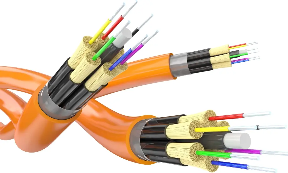
The colors of the optical fibers inside fiber optic cables
1.1 What are fiber optic cable color codes?
Typically, a fiber optic cable contains one or more optical fibers made of glass or plastic at its core. Surrounding the core is the cladding layer, which reflects light, and the outermost layer is the outer sheath. The outer sheath is designed to safeguard the entire fiber cable. Components such as the outer sheath, the inner fibers, and even the fiber connectors often have different colors.
Fiber optic cable color codes are a standardized color system used to identify each fiber within a cable. Each fiber is marked with a distinct color, making it easier for network technicians to splice, trace, and troubleshoot connections. This is especially important when working with cable runs containing dozens or even hundreds of fibers.
1.2 EIA/TIA-598 standard for fiber optic color codes
The TIA-598 fiber color code system was established by the Telecommunications Industry Association (TIA) and the Electronic Industries Alliance (EIA) in the United States. It is an industry standard used to identify fiber colors, enabling faster and more accurate installation, maintenance, and management of optical networks.
The EIA/TIA-598 standard, issued by the TIA, is the most widely used color coding system for optical fibers. It defines a set of standard colors, such as blue, orange, green, brown, red, black, yellow, and others, to differentiate individual fibers.
According to TIA/EIA-598, fiber optic color codes are categorized into three main groups:
- The outer sheath of the cable
- The sequence of fibers inside the cable
- The fiber optic connectors
DIN VDE 0888 standard specifies the symbols printed on the surface of optical cables.
1.3 Fiber optic cable color codes and markings according to IEC 60794 and DIN VDE 0888
In the European fiber optic industry, IEC 60794-1-1 and DIN VDE 0888 are often applied together but serve different purposes:
- IEC 60794-1-1: Specifies the color sequence of fibers inside a cable. This international standard defines the color of each fiber (for example, starting with Red instead of Blue, as in the US TIA standard).
- DIN VDE 0888: Focuses on markings printed on the cable surface. This standard provides a system of letters and numbers to describe the cable structure and materials, such as:
- Sheath type (PVC, PE, PUR, etc.)
- Reinforcement type (steel, non-metallic reinforcement fibers, etc.)
- Number of fibers, core diameter, bandwidth, design wavelength, and more
When both standards are applied together:
- IEC ensures consistent color coding for splicing and testing.
- DIN VDE 0888 provides standardized markings on the cable sheath, allowing quick identification of technical specifications, installation location (indoor, outdoor, or mixed), and environmental resistance.
2. The importance of color coding in fiber optic systems
Fiber optic cable color codes make identification and installation easier and faster.
In large-scale network infrastructures, fiber optic color codes are a core element for efficient management, installation, and maintenance. A single fiber cable can contain 12, 24, or even 144 fibers, making it impossible to distinguish individual fibers by sight alone. Color codes become a “common language” that allows technicians to easily identify, handle, and expand the network.
- Ensuring accurate connections: Color codes enable technicians to splice and terminate fibers correctly, preventing confusion between fibers, maintaining stable signals, and reducing signal loss.
- Preventing cross-connections: Clear identification of each fiber helps avoid incorrect or crossed connections, a common cause of network interruptions or performance degradation.
- Supporting testing and troubleshooting: During measurements or troubleshooting, color codes allow technicians to quickly locate and work on the correct fiber, reducing maintenance time and minimizing technical errors.
- Maintaining organized systems during expansion: When expanding a network, color codes help organize and manage multi-fiber bundles systematically, keeping the infrastructure clear and easy to track.
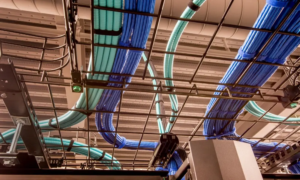
The application of fiber optic cable color coding in large data centers
2.2 Practical applications of fiber optic cable color codes
Fiber optic color codes are an indispensable tool for ensuring fast and accurate installation and maintenance. Here are some typical examples of how color codes are applied in practice:
- Connections between buildings (Campus network): Outdoor fiber routes connecting multiple buildings often contain multiple buffer tubes with hundreds of fibers. Color codes help technicians accurately identify the tube and fiber to be spliced, reducing the time needed for emergency repairs.
- FTTH deployment (Fiber To The Home): In fiber-to-the-home projects, color codes are used to manage the distribution of fibers from the central office to individual customer premises. As the number of subscribers increases, colors ensure that each connection is correctly assigned and documented, preventing confusion.
- Inside data centers: Technicians rely on fiber color charts to trace connections between patch panels and server racks. When a transmission line encounters a problem, the correct color coding allows them to quickly isolate the faulty fiber without affecting other connections.
3. Fiber optic cable color codes according to the TIA/EIA-598 standard
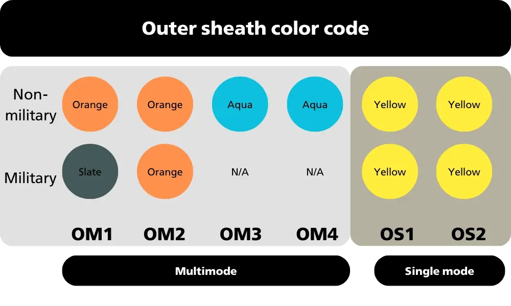
Outer sheath color codes for single mode and multimode optical cables according to the EIA/TIA-598 standard
The fiber color coding system under the TIA/EIA-598 standard is divided into three main groups: cable sheath, internal fibers, and connectors.
3.1 Color codes for the outer sheath of single mode and multimode optical cables
Fiber cables used in outdoor or internal networks (such as distribution cables and patch cables) often have different sheath colors or printed markings for easy identification.
The EIA/TIA-598 standard specifies color codes for each fiber type, allowing users to easily recognize cables containing a specific fiber type based on the sheath color:
- Multimode 50/125 (OM2): Orange
- Multimode 50/125 (OM3, OM4): Aqua
- Multimode 50/125 (OM5): Lime Green
- Multimode (OM1): Orange
- Multimode (100/140): Orange
- Single mode (OS1, OS1a, OS2): Gold
- Polarization-maintaining single mode: Blue
For tactical fiber optic cables used in television and military applications, the color codes differ in some places:
- Multimode 50/125 (OM2): Orange
- Multimode 50/125 (OM3, OM4): Not specified
- Multimode 50/125 (OM5): Not specified
- Multimode (OM1): Slate
- Multimode (100/140): Green
- Single-mode (OS1, OS1a, OS2): Gold
- Polarization-maintaining single mode: Undetermined
Fiber optic color code according to EIA/TIA-598 standard
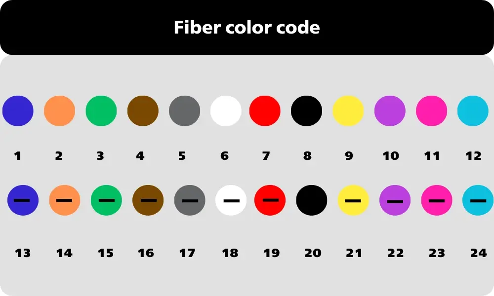
3.2 Fiber color codes
To facilitate identification, the fibers inside a cable are color-coded. Classification is based on the number of fibers within the cable:
- For fiber cables with fewer than 12 fibers: Each fiber is marked with a distinct color, allowing individual identification.
- For fiber cables with more than 12 fibers (e.g., 24 fibers): The color sequence follows 1 to 12 and then repeats. However, the second group of fibers will have a distinguishing mark, such as a colored stripe or other symbol, to differentiate them.
Standard color codes for 12 fibers:
| Sequence number | Color |
| 1 | Blue |
| 2 | Orange |
| 3 | Green |
| 4 | Brown |
| 5 | Slate |
| 6 | White |
| Sequence number | Color |
| 7 | Red |
| 8 | Black |
| 9 | Yellow |
| 10 | Purple |
| 11 | Rose |
| 12 | Aqua |
Fiber optic connector color code according to EIA/TIA-598 standard
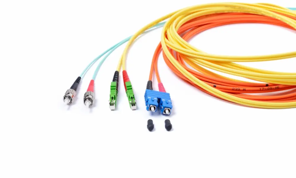
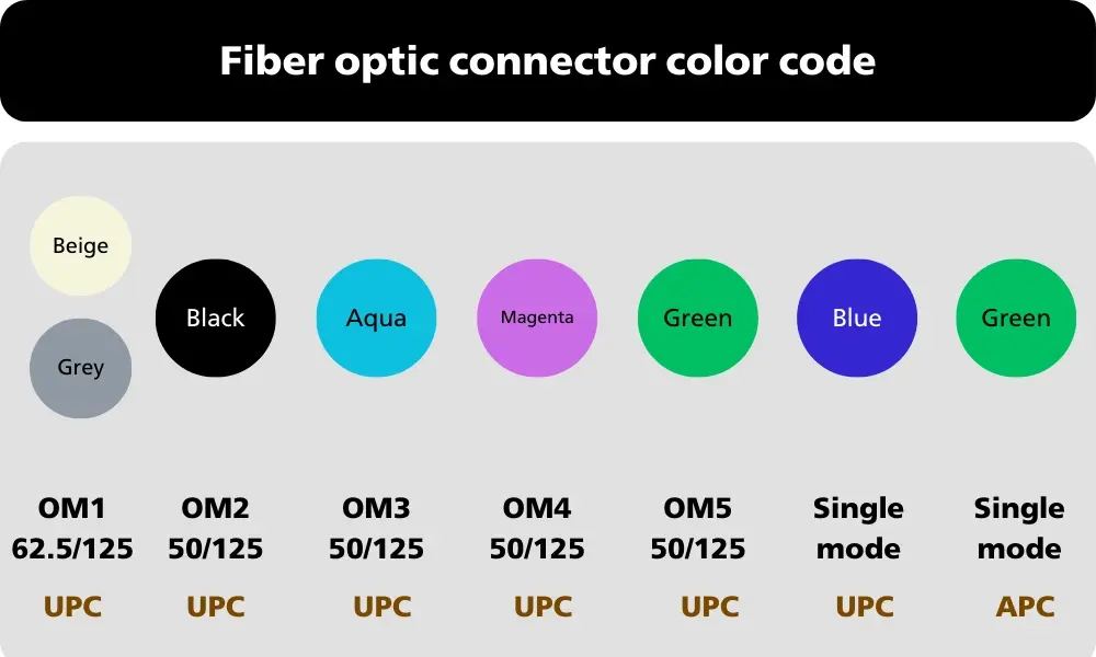
3.3 Fiber optic connector color codes
Although fiber optic connectors such as SC, LC, MPO, and other variants are commonly used, connector colors are primarily based on two factors:
- Fiber type
- Polish type (UPC or APC)
Based on this color code, technicians can quickly identify the type of fiber optic cable and connector standard for accurate installation and maintenance.
| Type of optical fiber | Polish Style | Color |
| Multimode OM1 62.5/125 fiber optic cable | UPC | Be/Gray |
| Multimode OM2 50/125 Fiber Optic Cable | UPC | Black |
| Multimode OM3 50/125 Fiber Optic Cable | UPC | Blue |
| Multimode OM4 50/125 fiber optic cable | UPC | Magenta (purple-red/red-purple) |
| Multimode OM5 50/125 Fiber Optic Cable | UPC | Green |
| Single mode fiber optic cable | UPC | Blue |
| Single mode Fiber Optic Cable | APC | Green |
4. Fiber optic cable color codes and markings according to IEC 60794 and DIN VDE 0888
Optical fiber color code according to IEC standard
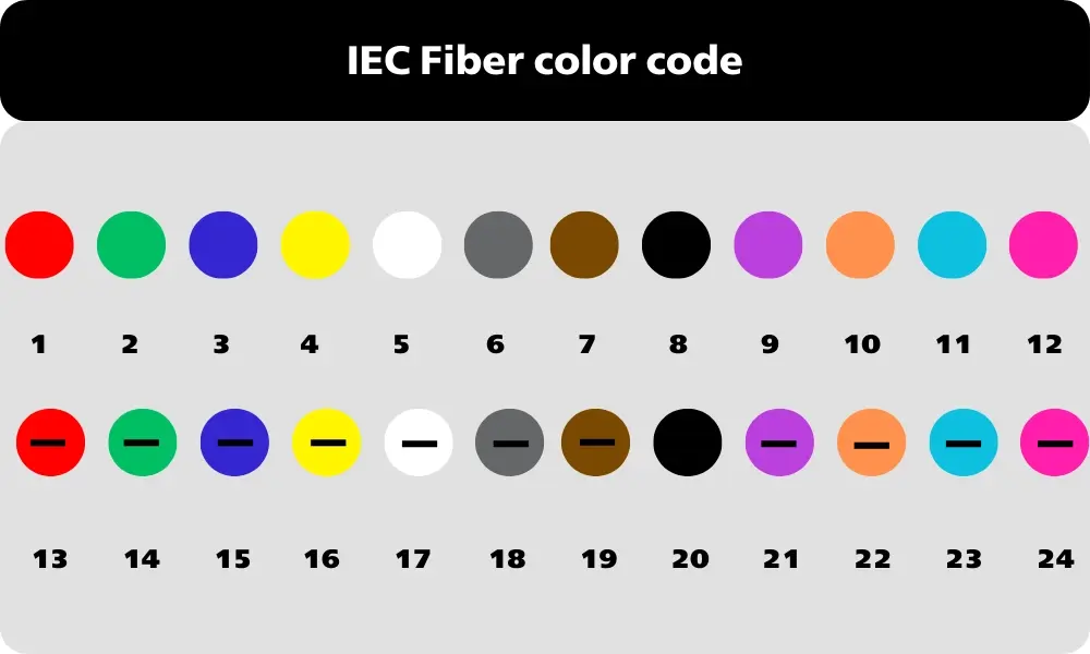
4.1 Fiber color codes according to IEC 60794
Although the TIA standard is considered a global benchmark, it is not the only system in use. In Europe and some parts of Asia, the IEC 60304 and IEC 60794 standards are also widely applied, creating a “parallel system” that can be confusing if not fully understood.
The main difference lies in the color sequence of fibers inside the cable. For example, the IEC standard starts with fiber 1 as Red, whereas TIA specifies Blue for fiber 1. This difference highlights the importance for installers to understand which standard applies in their region and to accurately identify the specific standard for each project. Misidentifying the standard can lead to serious errors in international telecommunications projects.
| Sequence number | Color |
| 1 | Red |
| 2 | Green |
| 3 | Blue |
| 4 | Yellow |
| 5 | White |
| 6 | Gray |
| Sequence number | Color |
| 7 | Brown |
| 8 | Purple |
| 9 | Turquoise |
| 10 | Black |
| 11 | Orange |
| 12 | Red |
4.2 Fiber optic cable symbols according to DIN VDE 0888 standard
The DIN VDE 0888 standard defines a system of characters and color codes for fiber optic cables, allowing quick identification of technical characteristics for design, installation, and maintenance. Each position in the character string provides specific information about the cable’s structure and properties:
- Cable type: I (Indoor), A (Outdoor), AI (Outdoor/Indoor), AT (Outdoor fan out).
- Buffer type: V (Tight buffer), K (Composite buffer), H (Loose buffer without gel), B (Loose buffer with gel), D (Multifibre buffer without gel), M (Multifibre buffer with gel).
- S: metal components in cables
- F (filling the cable core with petroleum jelly), Q (expanding material)
- Protective sheath: Y (PVC), 2Y (PE), 4Y (PA), 11Y (PUR), (L)2Y (PE-laminated), (2N)2Y, (L)(2N)2Y
- Reinforcement class: B (Armor), BY (Armor + PVC), B2Y (Armor + PE).
- Number of strands/bundle specifications: number of strands, number of strands per bundle, or number of bundles of strands.
- Optical fiber design: E (Single mode), G (Graded-index multimode).
- Core diameter (µm) for GI fiber or field mode diameter for single-mode fiber.
- Reflective layer diameter - cladding (micrometers).
- Signal attenuation: Attenuation coefficient (dB/km).
- Standard wavelengths: B (850 nm), F (1300 nm), H (1550 nm).
- Bandwidth/Dispersion parameters: in MHz·km or ps/nm·km.
- Outer braid type: identification parameters for the braid structure (lg layerstranding).
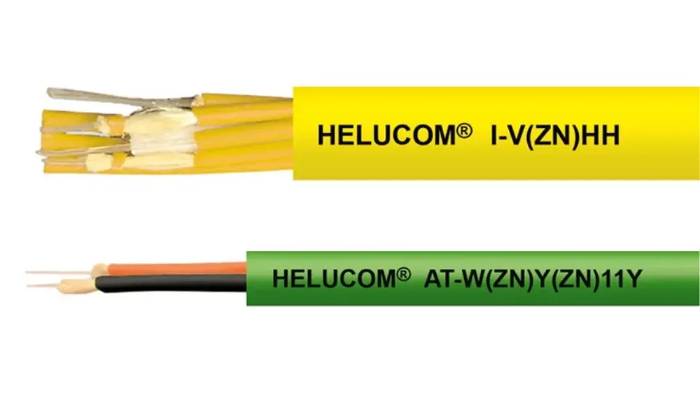
5. Types of fiber optic cables from HELUKABEL
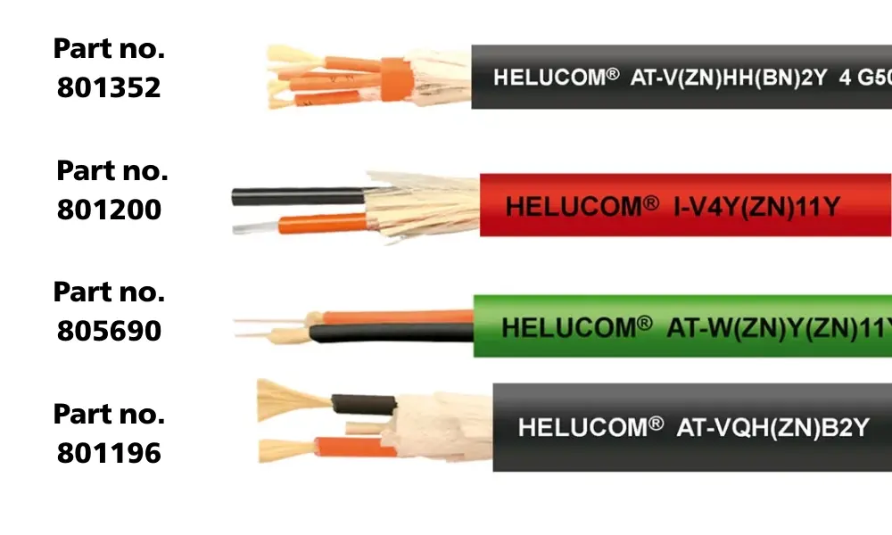
Fiber optic cables for industrial applications
All HELUCOM® fiber optic cables from HELUKABEL are designed in compliance with the DIN VDE 0888 standard, ensuring stable data transmission, easy maintenance, and international compatibility for telecommunications and industrial network systems.
Within the HELUCOM® product line, a full range of common fiber types is available, including standard fiber sizes such as 9/125 µm, 50/125 µm, and 62.5/125 µm.
HELUKABEL offers a wide variety of fiber optic cables to meet the demands of modern data transmission, such as:
5.1 Fiber optic cables for industrial applications
Modern manufacturing facilities require reliable data transmission to connect machines, sensors, and control systems.
- Multimode fiber optic cables: Suitable for medium-distance data transmission.
- Single-mode fiber optic cables: Designed for long-distance transmission with minimal signal loss.
- Cables for dynamic applications (drag chain): Specially engineered to withstand continuous bending, with an outer sheath resistant to oil, lubricants, and chemicals.
Some notable products include:
| Type of optical cable | Some fiber optic products | Single mode | Multimode | Part number |
| Industrial Cable GOF | AT-V(ZN)H(ZN)11Y | ✓ | ✓ | 803346 |
| AT-V(ZN)HH(ZN)B2Y | ✓ | 801352 | ||
| Industrial Cable POF | I-V4Y(ZN)11Y | 801200 | ||
| I-V4Y(ZN)Y | 801280 | |||
| Breakout Cable for Profibus/PROFINET | AT-VYY | ✓ | 800126 | |
| AT-W(ZN)Y(ZN)11Y | ✓ | 805690 | ||
| Industrial Cable HCS | AT-VQH(ZN)B2Y | HCS | 801196 | |
| I-V(Zn)YY | HCS | 801733 | ||
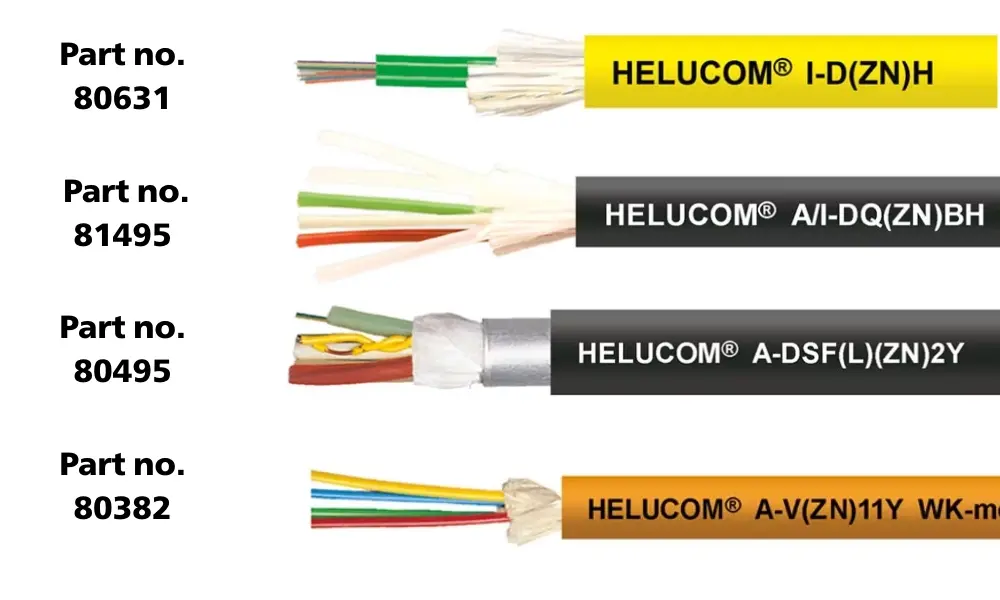
Certain types of fiber optic cables used for infrastructure
5.2 Fiber optic cables for infrastructure
As the internet and cloud computing increasingly form the backbone of business operations, the demand for building and expanding data centers continues to rise. One of the key future trends in electrical infrastructure is the growing use of fiber optic cabling.
Data centers, telecommunications networks, and power distribution systems require outdoor fiber optic cables to interconnect buildings and residential areas, creating the internet backbone for high-speed broadband connections. With high bandwidth capacity and ultra-low latency, fiber optic cables are the ideal choice for both intra-data-center networks and inter-data-center links.
Some typical fiber optic cable lines include:
| Type of optical cable | Some fiber optic products | Single mode | Multimode | Part number |
| Indoor cables | I-D(ZN)H | ✓ | ✓ | 80631 |
| I-V(Zn)H | ✓ | ✓ | 80435 | |
| Universal cable | FS120 AI-DQ(ZN)(SR)H | ✓ | ✓ | 11017450 |
| A/I-DQ(ZN)BH Stranded | ✓ | ✓ | 81495 | |
| Outdoor cable | A-DQ2Y Stranded | ✓ | 803931 | |
| A-DSF(L)(ZN)2Y HYBRID | ✓ | 80495 | ||
| Aerial cable | ADSS | ✓ | 82390 | |
| ADSS L | ✓ | 804733 | ||
| Mobile cable | WK A-V(ZN)11Y TRAILING | ✓ | ✓ | 80382 |
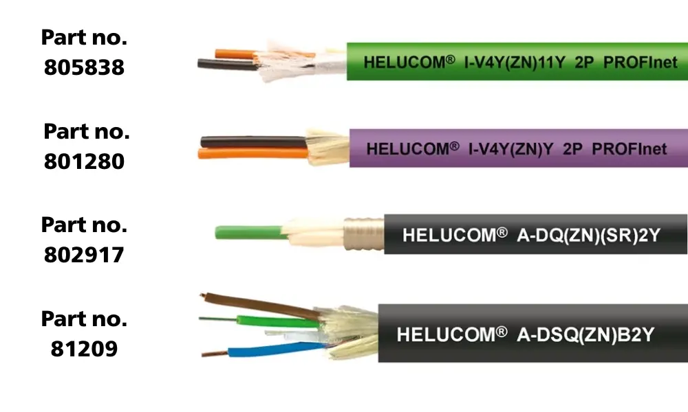
Fiber optic cables for other fields such as healthcare, defense, and security
5.3 Fiber optic cables for medical, defense, and security sectors
In addition to the telecommunications sector, medical technology also utilizes fiber optics in endoscopic devices, microscopes, and various imaging techniques. Fiber optic cables are further employed in sensors, spectrometers, and a wide range of optical instruments.
High-durability fiber optic connectors are used in defense and security technologies, ensuring reliable performance in demanding environments. Moreover, fiber-optic measurement methods leverage the fiber itself as a sensor for monitoring temperature and structural integrity - such as detecting cracks in bridges or pinpointing leaks in dams with high precision.
| Application | Fiber optic cable products | Characteristics | Technical specifications | Part number |
| Medical – endoscopy equipment, microscopes, optical imaging | I-V4Y(ZN)Y | Low attenuation, high flexibility | Attenuation: 160A1 Minimum bending radius: 100 - 120 | 801280 |
| I-V4Y(ZN)Y | 805838 | |||
| National defense and security | A-DQ(ZN)(SR)2Y | Steel armor, rodent-proof, water-resistant | Minimum bending radius: up to 350 | 802917 |
| A-DF(Zn)₂Y(Sr)₂Y | 82190 | |||
| Measurement and monitoring applications | A-DSQ(ZN)B2Y | Heat resistance, moisture resistance, long-distance transmission capability | Minimum bending radius: up to 430 | 81209 |
| A-DSF(L)(ZN)2Y | 80495 |
If you still have questions, don't hesitate to contact HELUKABEL Vietnam's team of engineers for detailed answers.
HELUKABEL® Vietnam
| Address | 905 Nguyen Kiem Street, Hanh Thong Ward, Ho Chi Minh City 700000 |
| info@helukabel.com.vn | |
| Hotline | +84 28 77755578 |
| Website | www.helukabel.com.vn |
| Discover and purchase our products on | Tiki | Shopee | Lazada | Product finder |
| Connect with us on | Facebook | LinkedIn | Instagram | YouTube | Zalo | WhatsApp | TikTok | Spotify |