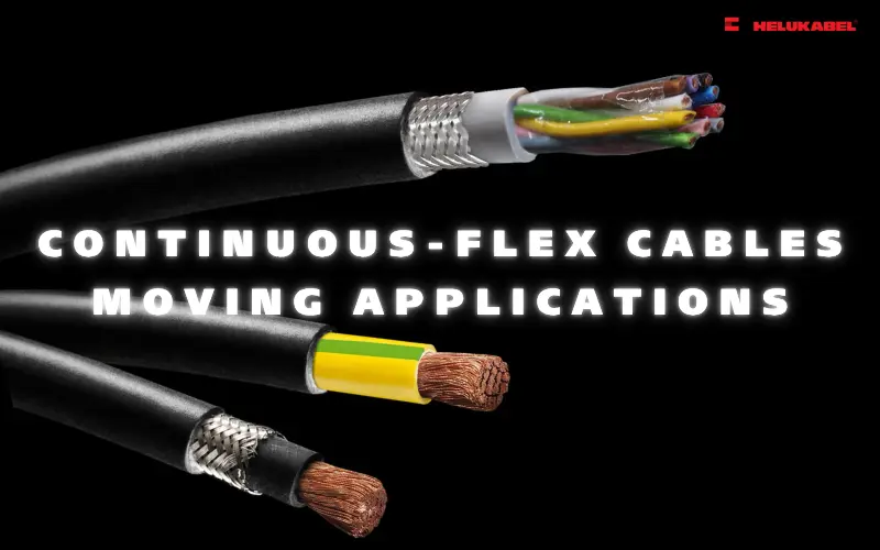
Crosstalk in data cables – Anti-interference solutions from HELUKABEL
Crosstalk is a common limitation when using copper data cables in communication systems. However, when properly managed and controlled, it can be significantly reduced, ensuring reliable signal transmission and making copper cables a suitable choice for various applications.
Table of content
Data cables play a fundamental role in modern industrial operations, particularly in running network systems and automated production lines. However, in industrial environments, crosstalk is a common challenge - it can distort signals, disrupt data transmission, and negatively impact the overall system performance.
1. What is crosstalk in data and network cables?
Crosstalk is the interference between electromagnetic signals that occurs when the electromagnetic field from one conductor affects a neighboring conductor, distorting or degrading the signal transmitted through the network cable. In environments that demand high accuracy and stability such as data centers, server rooms, or industrial control systems - crosstalk can significantly impact network performance, data transmission stability, and may even cause device malfunctions.
In industrial automation and communication systems, crosstalk is particularly common in systems using copper conductors, such as unshielded twisted pair (UTP) cables or coaxial copper cables.
The phenomenon arises from coupling between parallel signal paths. The main causes are electrostatic induction and electromagnetic induction. Each signal generates an electric and magnetic field around it; when these fields overlap between adjacent conductors, crosstalk occurs, distorting the signal and affecting the accuracy of transmitted data.
2. Types of crosstalk
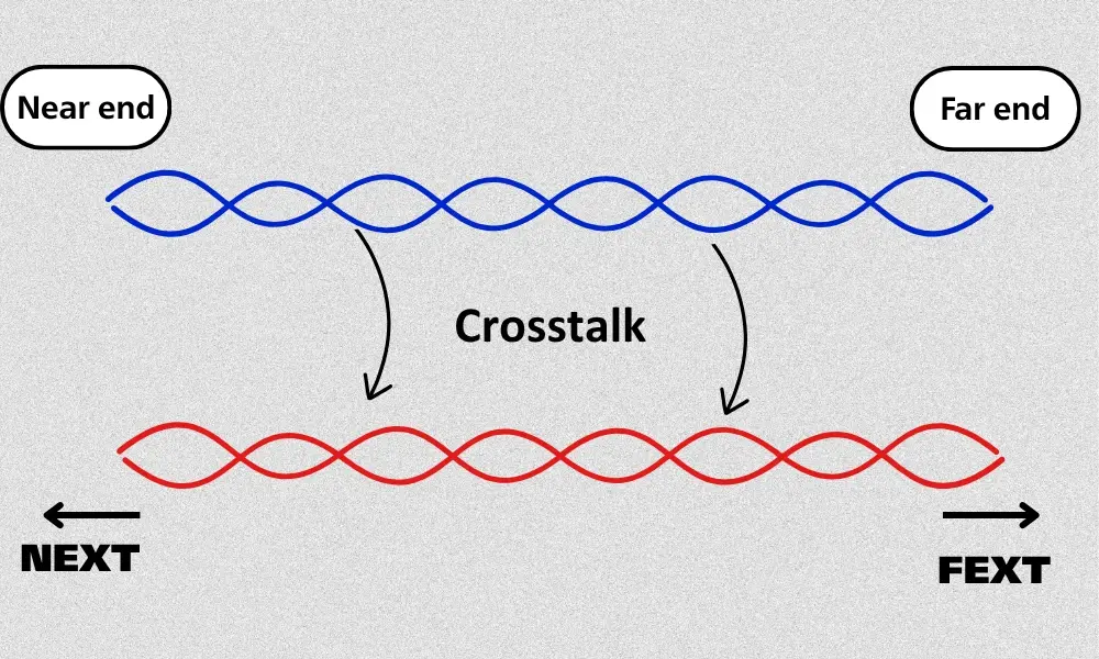
Near-end crosstalk (NEXT) and far-end crosstalk (FEXT)
In industrial communication and network systems, crosstalk does not occur in a single form but is generally classified into two main types, each affecting signals differently: Near-end crosstalk (NEXT) and far-end crosstalk (FEXT).
2.1 Near-end crosstalk (NEXT)
NEXT is the most common type of interference in systems using twisted-pair data cables. It occurs when the signal from one twisted pair induces electromagnetic interference onto an adjacent pair at the near end - the end where the signal is transmitted or received.
NEXT is often used as a key technical metric to evaluate a network cable’s crosstalk resistance. The lower the NEXT value, the higher the cable quality, as it indicates better protection of signals from interference between pairs.
2.2 Far-end crosstalk (FEXT)
Unlike NEXT, FEXT occurs at the far end of the cable - the end opposite the signal source. In other words, as the signal travels along the cable, a portion of its electromagnetic energy may couple into neighboring pairs, generating interference at the receiving end.
FEXT generally has less impact than NEXT because the induced interference diminishes over distance. However, in high-speed networks such as Gigabit Ethernet or 10 Gigabit Ethernet, the combined effect of NEXT and FEXT can significantly degrade signal quality, affecting both transmission speed and stability.
3. Impact of crosstalk on data cable and network systems
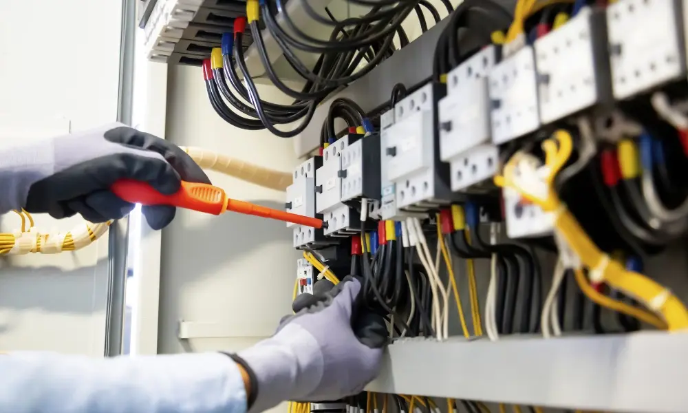
Crosstalk can cause signal attenuation, distortion, or even leakage of information in data centre, control cabinet
Crosstalk presents a significant technical challenge in many industrial data transmission systems:
3.1 Communication systems
In communication systems, crosstalk can cause signal attenuation, distortion, or even leakage of information from one channel to another. When signals are transmitted as electrical currents over copper data cables, they generate electromagnetic fields (EMF) that affect adjacent conductors, resulting in electromagnetic interference (EMI). This directly impacts the accuracy, speed, and reliability of data transmission.
3.2 Networking systems
In LANs or high-speed data networks, crosstalk can reduce the Signal-to-Noise Ratio (SNR), leading to packet loss, decreased bandwidth, or temporary connection drops. This often occurs when copper cables run parallel over long distances or when unshielded twisted-pair (UTP) cables are deployed in environments with high electromagnetic interference from nearby equipment.
3.3 Printed Circuit Boards (PCBs)
On PCBs, crosstalk occurs when traces are routed too close to each other, causing electromagnetic coupling. If a signal trace carries high currents or rapidly changing voltages, it can induce interference on adjacent traces, distorting signals and impacting the overall performance of electronic devices.
4. Top 6 methods to reduce crosstalk in data and LAN cable systems
In today’s fast-evolving communication technology landscape, minimizing crosstalk has become a critical factor to ensure the performance, stability, and reliability of data cable systems. There are several technical measures available to control - or nearly eliminate crosstalk, ranging from cable material design and proper cable layout to precise installation and maintenance practices.
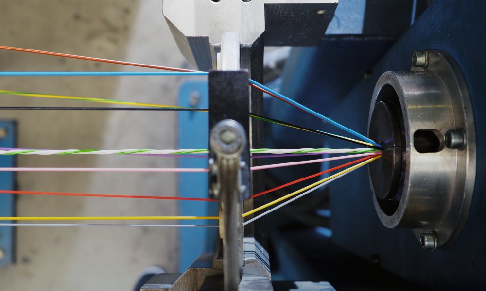
4.1 Increasing the twisting frequency of conductors
Twisted-pair cables are one of the most practical and effective solutions to reduce crosstalk in data transmission systems. Within the cable, copper conductors are twisted together in a helical pattern, which helps cancel out electromagnetic interference between wire pairs.
- The tighter the twists, the more effective the cable is at reducing crosstalk.
- However, increasing the number of twists can also enlarge the overall cable diameter and affect its flexibility.
Twisting the two wires causes them to alternate positions relative to external interference along the entire cable length. As a result, on average, each wire occupies the same “average position” relative to the interference source. Specifically:
- In one section, wire A may be closer to the interference source than wire B.
- In the next section, wire B is closer than wire A.
This alternating pattern balances and gradually cancels out electromagnetic interference, significantly reducing crosstalk and improving signal quality.
Example: Cat6 cables have tighter twists and a more refined structure compared to Cat5e, providing superior crosstalk resistance, more stable signals, and higher transmission speeds.
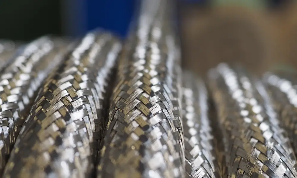
Shielded cables help to minimize crosstalk
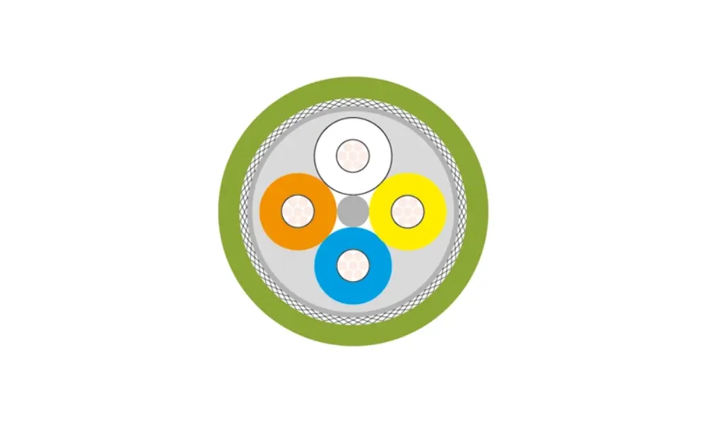
4.2 Using shielded data and LAN cables
Shielded cables are designed with a layer of metal or conductive material surrounding the conductor core, which helps block EMI from the external environment and reduces crosstalk between pairs within the cable.
Compared to unshielded twisted pair (UTP) cables, shielded cables are generally more expensive and less flexible. However, they provide cleaner and more stable signal transmission, making them ideal for industrial environments, server rooms, or data centers—where absolute transmission reliability is critical.
Common types of shielded LAN cables include:
- STP (Shielded Twisted Pair): Each pair of wires is individually wrapped in a metallic shield.
- FTP (Foiled Twisted Pair): All pairs are collectively wrapped in a single foil shield.
- S/FTP (Screened Foiled Twisted Pair): Combines both protections - each pair is individually shielded, and the entire bundle is wrapped in an overall foil, offering maximum interference protection.
4.3 Proper cable separation and layout
In high-density telecom systems or control cabinets, interference between modules can pose a significant challenge. When modules operate close to each other, their electromagnetic fields may overlap, causing crosstalk and degrading signal integrity.
Therefore, maintaining physical separation between cables plays a critical role in minimizing crosstalk. Effective mitigation measures include:
- Separate power and signal lines: Keep the maximum possible distance between them.
- Secure cable routing: During installation, fix cables along walls or floors and use dedicated conduits or cable trays to isolate signal lines.
- Use insulation or shielding if separation is limited: When complete physical separation isn’t feasible, electrically insulate or run cables through shielded conduits to reduce mutual interference.
- Ensure proper grounding for each module: Correct grounding helps control leakage currents and reduces the risk of electromagnetic interference.
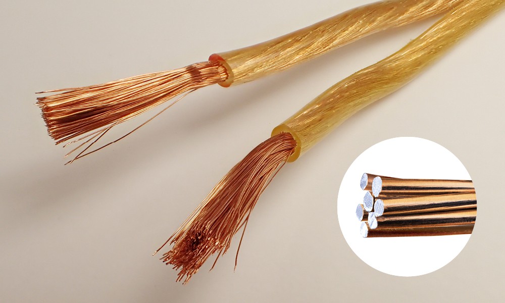
CCA conductor
4.4 Using pure copper data cables
The quality of the conductor material directly affects both noise immunity and data transmission stability.
- Pure copper cables offer higher electrical conductivity, lower signal loss, and superior resistance to interference compared to copper-clad aluminum (CCA) cables.
- Although CCA cables are more cost-effective, their performance degrades faster and the overall system lifespan is shorter, especially in high-demand data transmission environments.
Therefore, for industrial applications or enterprise network infrastructure, using pure copper data cables is recommended to ensure consistent performance, strong signal integrity, and long-term reliability across the entire system.
4.5 Avoid damaging or exceeding the cable’s bending radius
Maintaining the proper bending radius is crucial to prevent signal degradation and reduce crosstalk in network systems. Excessive bending can alter the cable’s impedance, leading to signal reflections and increased electromagnetic coupling between adjacent wire pairs.
Additionally, the twisted-pair structure inside the cable is key to its noise-canceling ability and signal integrity. If the cable is kinked, stretched, or subjected to heavy pressure, the internal twists can be deformed, making the cable more susceptible to interference and signal loss.
When installing network cables, it is important to:
- Maintain the minimum bending radius as recommended by the manufacturer.
- Avoid tightly bundling or clamping cables inside trays or conduits.
- Prevent mechanical damage and protect the cable with proper accessories to ensure long-term durability and optimal transmission performance.
Earthing technique can be used to reduced crosstalk
4.6 Reducing crosstalk using grounding techniques
Grounding plays a critical role in maintaining signal integrity and minimizing crosstalk in electrical and electronic systems.
When devices, modules, or circuit boards are interconnected through connectors or data cables, each signal requires a proper return path to complete the electrical circuit - this is the primary role of the ground wire.
If the return path is not properly designed, the signal may flow through unintended circuit paths, generating unwanted currents that cause crosstalk and electromagnetic interference (EMI). Proper grounding ensures stable signal return paths, reduces interference between adjacent signals, and enhances overall system reliability.
5. HELUKABEL data cables and crosstalk solutions
Technical measures are only part of the solution to minimize crosstalk. The key factor lies in selecting the right cables and accessories from the system design stage.
HELUKABEL offers a comprehensive range of electrical connectivity solutions, effectively controlling EMI and ensuring stable, reliable signal transmission—even in the most demanding industrial environments.
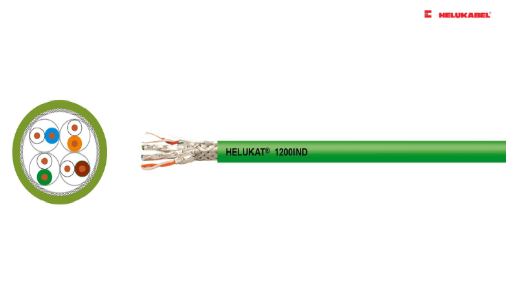
5.1 Shielded LAN cables
HELUKABEL provides a wide range of shielded twisted-pair network cables , including FTP, S/FTP, and SF/UTP types, meeting the highest transmission standards in environments with significant electromagnetic interference.
Some notable products include: HELUKAT® 1500 CAT.7A S/FTP FRNC STATIC, HELUKAT® 600 CAT.7 S/FTP FRNC FLEX, HELUKAT® 100T CAT.5e S/UTP PUR TORSION, HELUKAT® 100-PH120 CAT.5 F/UTP FR-0H…
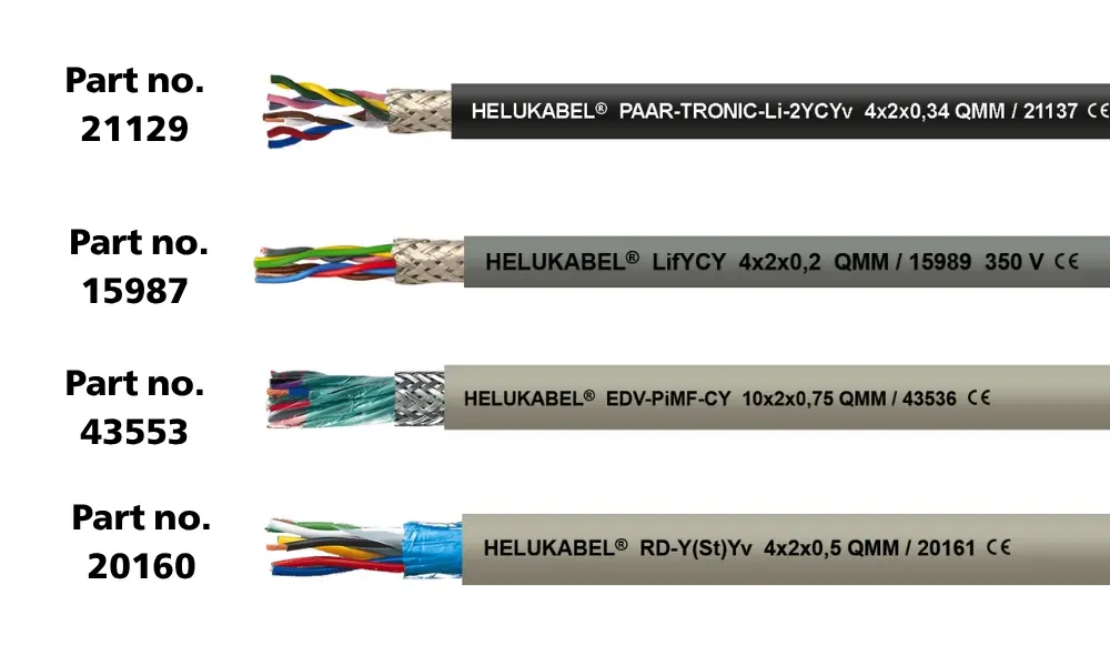
5.2 Shielded data cables
HELUKABEL offers a range of data cables with dense braided shielding, effectively minimizing EMI. Combined with twisted-pair construction, these cables provide optimal crosstalk attenuation, ensuring stable, high-quality signal transmission even in demanding industrial and networking environments.
| Cables | Features | Part no. |
| PAAR-TRONIC-CY | Special PVC outer sheath | 21001 |
| PAAR-TRONIC-Li-2YCYv / PAAR-TRONIC-Li-2YCY | PE insulation, compatible with RS485 and RS422 interface | 21129 / 21111 |
| LifYCY | Flexible installation cable | 15987 |
| EDV-PiMF-CY | PE insulation | 43553 |
| RD-Y(St)Y (inside) / RD-Y(St)Yv (outside, underground) | Supports analog and digital signals up to 10 kHz | 20140 / 20160 |
| RD-H(St)H | Halogen-free, suitable for indoor and outdoor use (non-UV resistant) | 20200 |
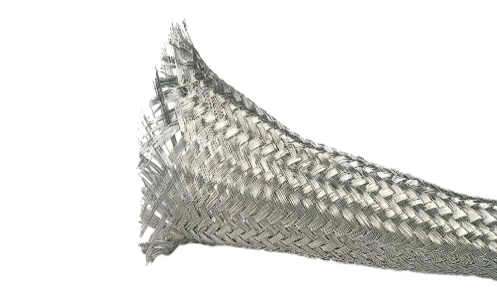
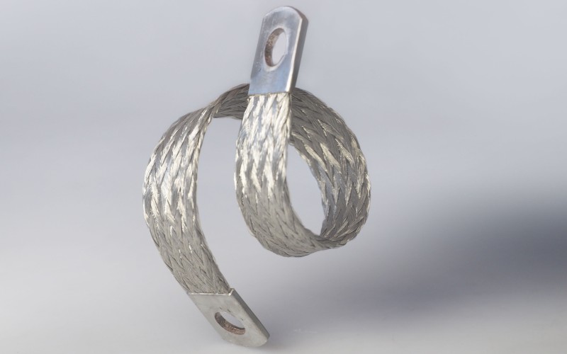
Braided sleeves - cable protection accessories
Products for potential earthing concept of HELUKABEL
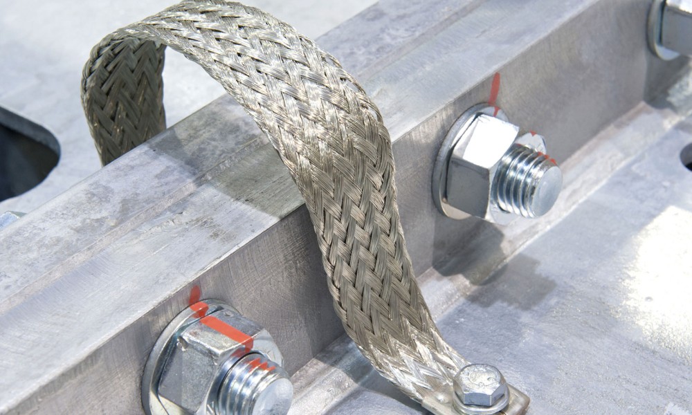
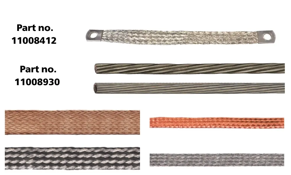
5.3 Products for grounding/earthing concept from HELUKABEL
- HELU-MB-Cuv earthing strap Made of tinned copper, providing superior electrical conductivity (Part no. 11008412)
- HELUPOWER® CU-CONDUCTOR-CL2 TINNED Class 2: Tinned copper with multi-strand construction (Part no. 11008930)
- HELUPOWER® CU-CONDUCTOR-CL5 TINNED Class 5: Fine-stranded tinned copper for higher flexibility (Part no. 11008942)
If you still have any concerns or questions, don't hesitate to reach out to HELUKABEL Vietnam's engineering team promptly for detailed assistance.
HELUKABEL® Vietnam
| Address | 905, Nguyen Kiem Street, Hanh Thong Ward, Ho Chi Minh City 700000, Vietnam |
| info@helukabel.com.vn | |
| Hotline | +84 28 77755578 |
| Website | www.helukabel.com.vn |
| Discover our products and place orders | Tiki | Shopee | Lazada | Product finder |
| Follow us on | Facebook | LinkedIn | Instagram | Youtube | Zalo | WhatsApp | Tiktok | Spotify |